Installation Guidelines for AQUASTOP® DSHA or DSHA-UGL Expansion Joint Devices
- Clean the work area from dirt and debris.
- If the concrete surface (hereinafter referred to as the mounting area) (item 2) is contaminated with bitumen, cement milk, grease, or oils, it should be cleaned using appropriate methods.
- If there are pores and cavities on the mounting area surface along the expansion joint, exposed coarse aggregate, protruding reinforcement, visible concrete mixture segregation, or cracks in the concrete, repairs should be performed.
- The suitability of the mounting area should be checked using a 2000 mm long straightedge. The maximum allowable gap in the longitudinal direction between the concrete surface and the straightedge should not exceed 2 mm, and in the transverse direction no more than 1 mm.
- Place extruded polystyrene (item 4) into the expansion joint gap.
- After instrumental verification of the position of DSHA or DSHA-UGL expansion joint device sections (item 1) (hereinafter referred to as devices), mark drilling locations with an industrial marker through the mounting holes for hex head anchor screws with washer R-LX-06X075-HF (item 3) and countersunk head anchor screws R-LX-06X050-CS for wall structures (item 3.1) (hereinafter referred to as anchor screws), with a 180 mm pitch.
- Remove devices from mounting areas (item 2) and begin drilling holes. Holes for fasteners should be drilled with a 6 mm diameter to a depth exceeding the fastener length by 20 mm. Clean holes from drilling debris using compressed air or an industrial vacuum. Special attention should be paid to the selection of parameters and drill sharpening quality.
⚠️ Important! It is not advisable to drill holes through the device's mounting holes.
- To prevent damage and wear of the compensator, the device (item 1) should be set 2-3 mm below the finished floor level depending on the material of the floor finish (item 5) and the width of the expansion joint. Note: To avoid selecting devices with insufficient allowable movement capacity, it is advisable to choose devices with support spacing (A) greater than the actual expansion joint width (Bs).
- If the floor structure (item 5) is thicker than the device height (item 1), install a trapezoidal concrete base, wider than the device guide support area and of required height, using concrete of class not lower than B30 with aggregate fraction (gravel screening) - 5-10 mm. For this purpose, make notches on the load-bearing concrete surface and apply a primer (e.g., based on acrylic copolymers) for reliable bonding between old and new concrete. Repeat steps 6 and 7 of these guidelines.
- Place anchor screws into mounting holes and use a screwdriver to tighten until contact with the fixed expansion joint device section, leaving them slightly loosened. Final tightening of anchor screws should be performed after installation of the subsequent section. Sections are joined with a 150 mm offset of the guide seams relative to the compensator. Maximum tightening torque on the tool is 400 Nm.
- Install the floor structure (item 5) according to the project, depending on the room's purpose.
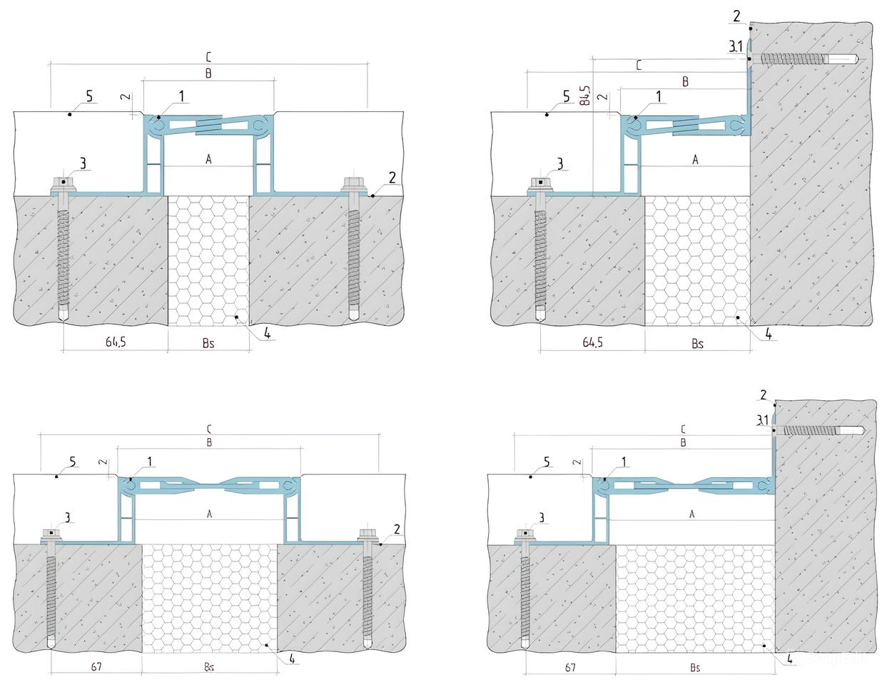
where:
- A - Support spacing of the expansion joint device;
- B - Visible width of the expansion joint device;
- C - Installation width of the expansion joint device;
- Bs - Actual width of the expansion joint.
For complex surface defects - contact OOO TD "GYDROMIX".


 Download Aquastop Product Catalog Part 2: Expansion Joint Devices