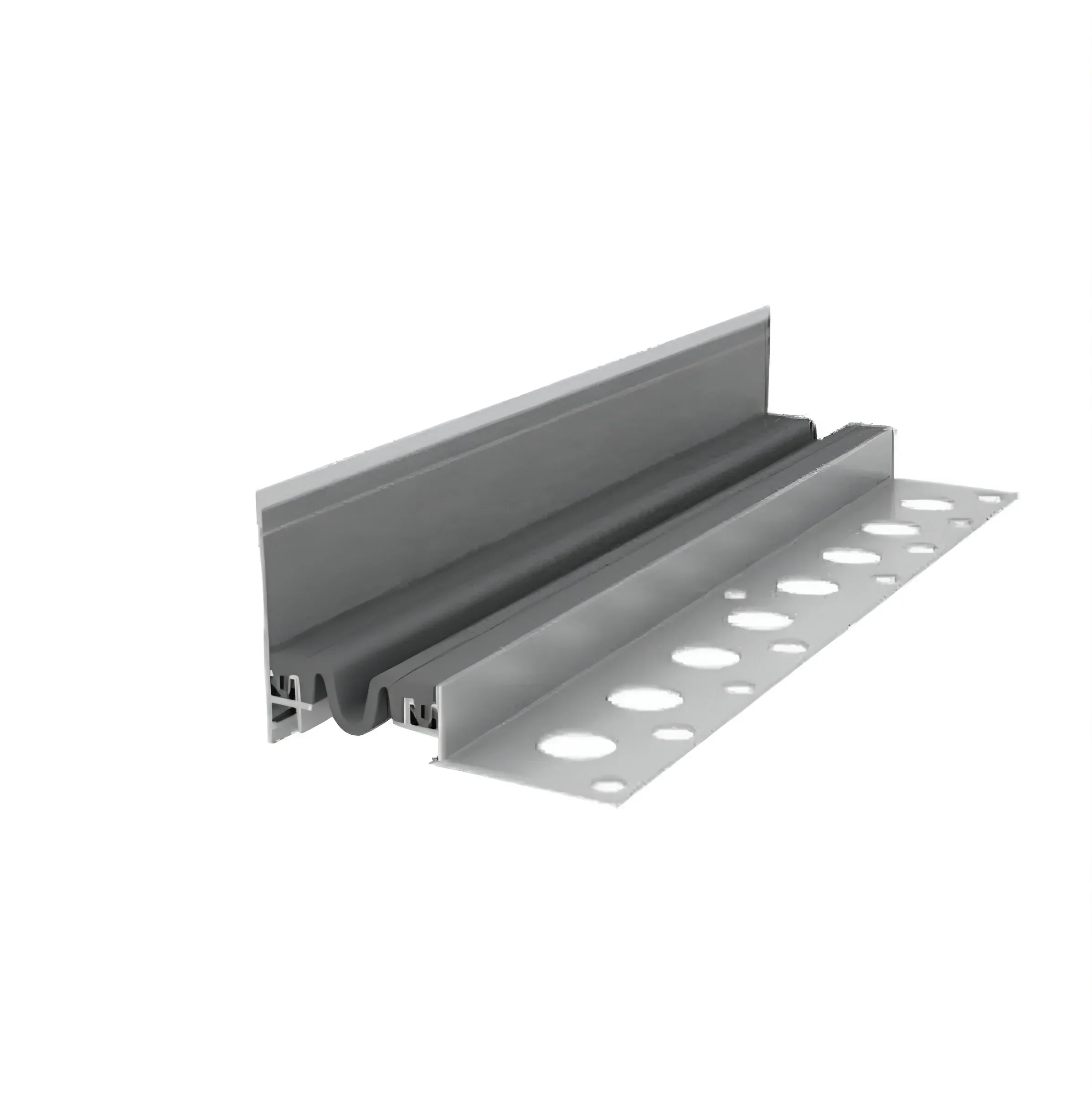
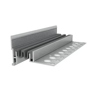
Installation Guidelines for AQUASTOP® DSHKA or DSHKA-ANG Expansion Joint Devices
- Clean the work area from dirt and debris.
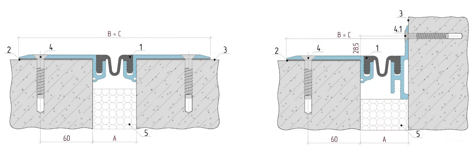
- If the concrete surface (hereinafter referred to as the mounting area) (item 3) is contaminated with bitumen, cement milk, grease, or oils, it should be cleaned using appropriate methods.
- If there are pores and cavities on the mounting area surface along the expansion joint, exposed coarse aggregate, protruding reinforcement, visible concrete mixture segregation, or cracks in the concrete, repairs should be performed.
- The suitability of the mounting area should be checked using a 2000 mm long straightedge. The maximum allowable gap in the longitudinal direction between the concrete surface and the straightedge should not exceed 2 mm, and in the transverse direction no more than 1 mm.
- Place extruded polystyrene (item 5) into the expansion joint gap.
- After instrumental verification of the position of DSHKA-0 or DSHKA-0-ANG expansion joint device sections (item 1) (hereinafter referred to as devices), mark drilling locations with an industrial marker through the mounting holes for countersunk head anchor screws R-LX-08X075-CS (item 4) and countersunk head anchor screws R-LX-06X050-CS for wall structures (item 4.1) (hereinafter referred to as anchor screws), with a 180 mm pitch (for every three linear meters of device).
- Remove devices from mounting areas (item 3) and begin drilling holes. Holes for fasteners should be drilled with 8 mm diameter (R-LX-08X075-CS) and 6 mm diameter (R-LX-06X050-CS) to a depth exceeding the fastener length by 20 mm. Clean holes from drilling debris using compressed air or an industrial vacuum. Special attention should be paid to the selection of parameters and drill sharpening quality.
⚠️ Important! It is not advisable to drill holes through the device's mounting holes.
- Apply primer to the cleaned and leveled mounting area surface and roll out GERLEN T 100/3 tape sealant (item 2) with a thickness of at least 3 mm and pressure of at least 1 MPa.
- Remove the protective film from GERLEN, apply primer, and install the device (item 1). Roll with pressure of at least 1 MPa.
Note: Prepare primer from GERLEN and "Kalosha" gasoline in a ratio of 1 kg to 3 liters. Primer viscosity should be 15-16 seconds in a VZ-4 viscometer funnel.
- Place device sections (item 1) on the tape sealant (item 2). Remove air bubbles with a roller using pressure of at least 1 MPa.
- Place anchor screws into mounting holes and use a screwdriver to tighten until contact with the device section, leaving them loosened. Final tightening should be performed after installation of the next section. Join sections with a 150 mm offset of the guide seams relative to the compensator. Join compensator using thermal welding at 185-195°C. Tightening torque:
- 900 Nm for R-LX-08X075-CS
- 400 Nm for R-LX-06X050-CS
where:
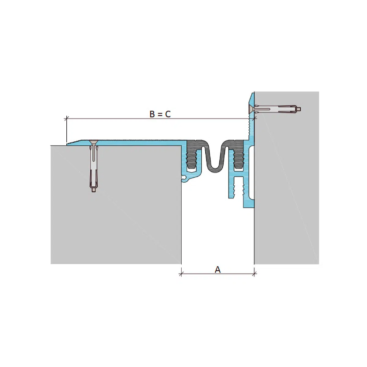
- A - Support spacing of the expansion joint device;
- B - Visible width of the device;
- C - Installation width of the device;
- Bs - Actual width of the expansion joint.
For non-standard defects - contact OOO TD "GYDROMIX".




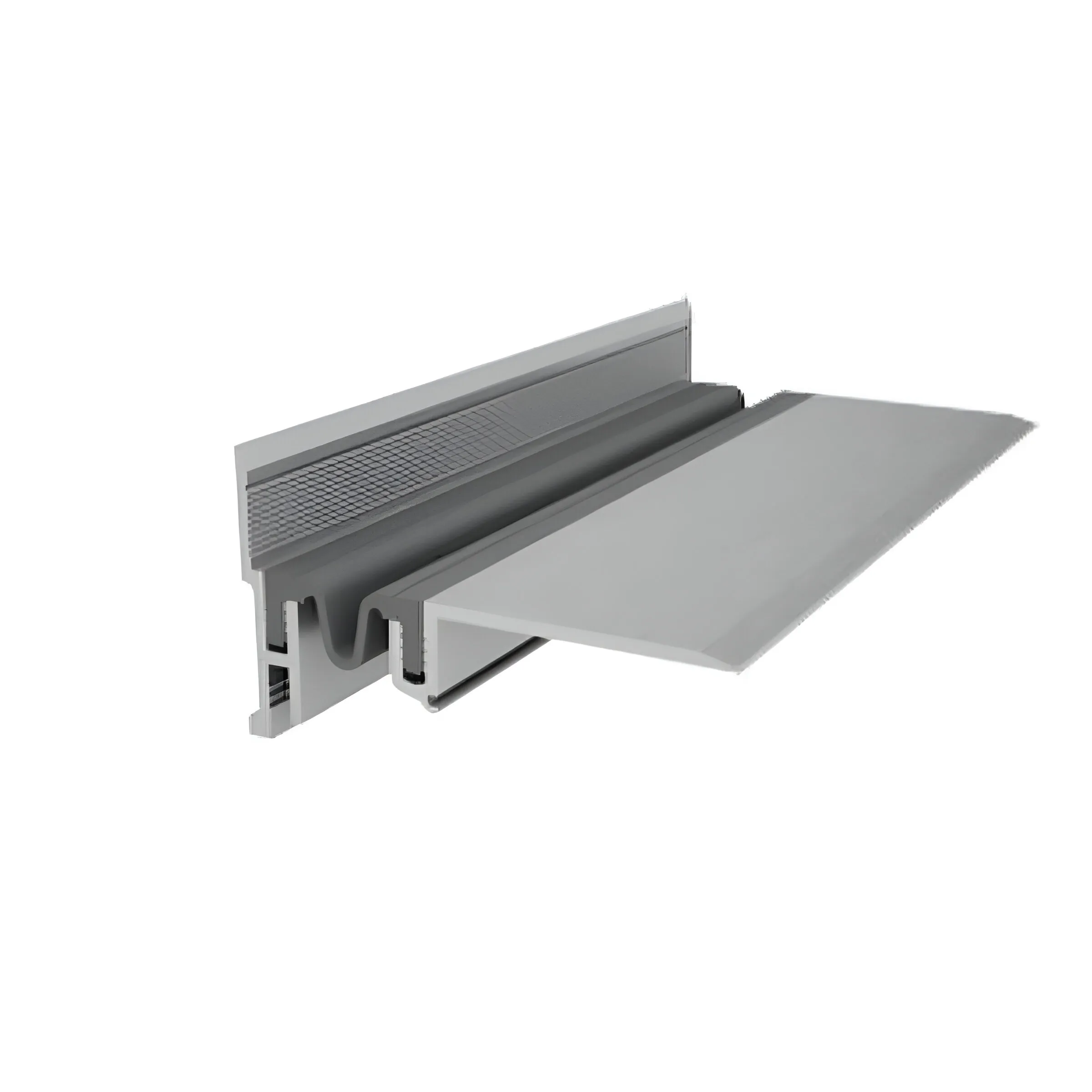


 Download Aquastop Product Catalog Part 2: Expansion Joint Devices